Concept
Is it possible to completely immerse an individual in a virtual world?
Yes, but in order to express a comprehensive and realistic world view, we need to engage the following senses:
- Sight: The ability to interpret the surrounding environment by processing information that is contained in visible light [1]
- Hearing: The ability to perceive sound by detecting vibrations [2]
- Touch: The faculty by which external objects or forces are perceived through contact with the body [3]
- Proprioception: The sense of the relative position of neighbouring parts of the body and the strength of effort being employed in movement [4]
- Equilibrioception: Sensory perception of orientation with respect to gravity [5]
So we need to be able to see and hear the virtual world, perhaps through a helmet equipped with a display and speakers. We need to be able to feel objects, impose force, and have force imposed upon us, perhaps through a haptic exoskeleton. And we need our perceived orientation with respect to gravity to match what we’re seeing in the virtual world, perhaps through a motion base or gimbaled system.
In Other Words…

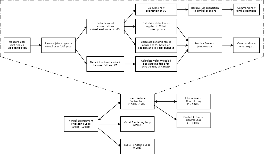
Or Perhaps A Little More Technically…
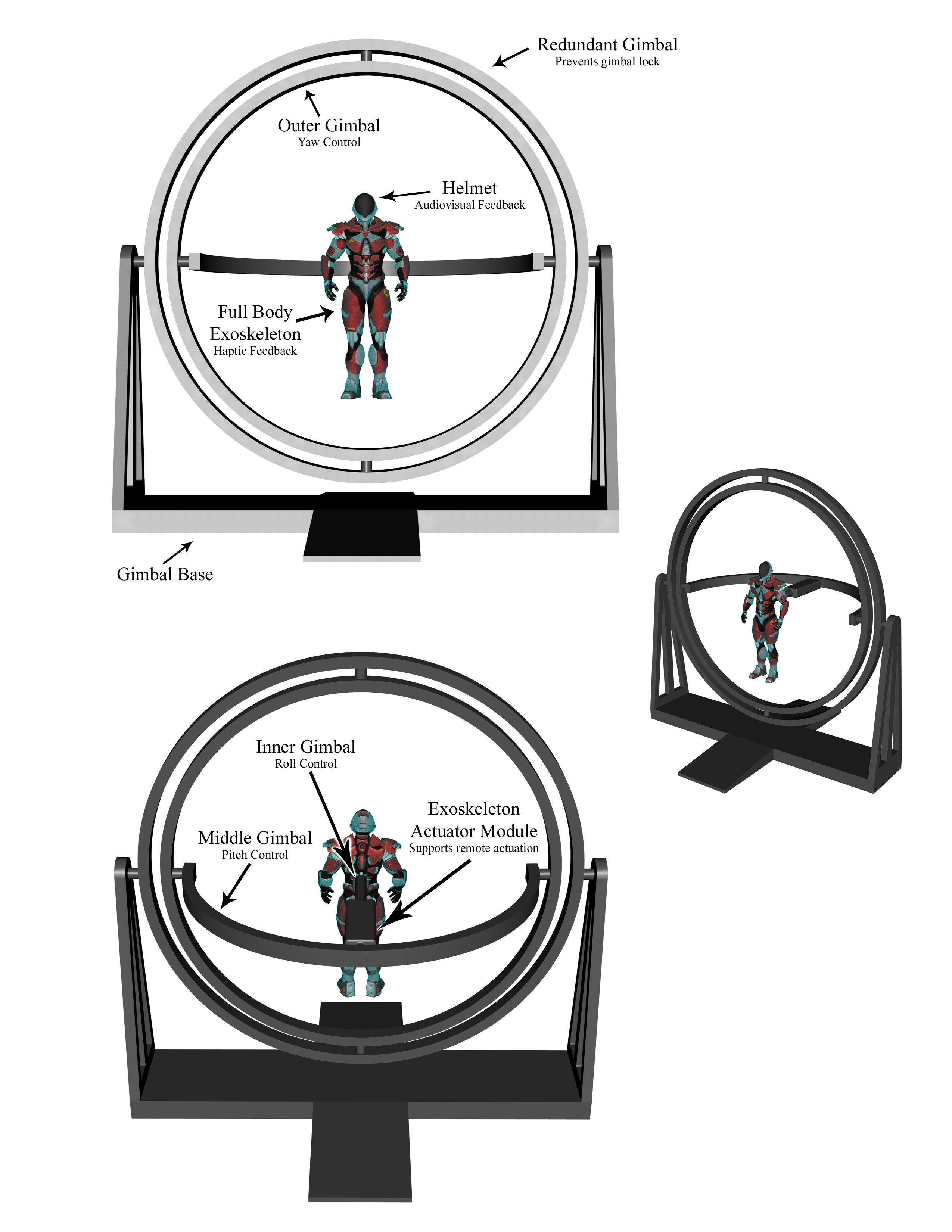
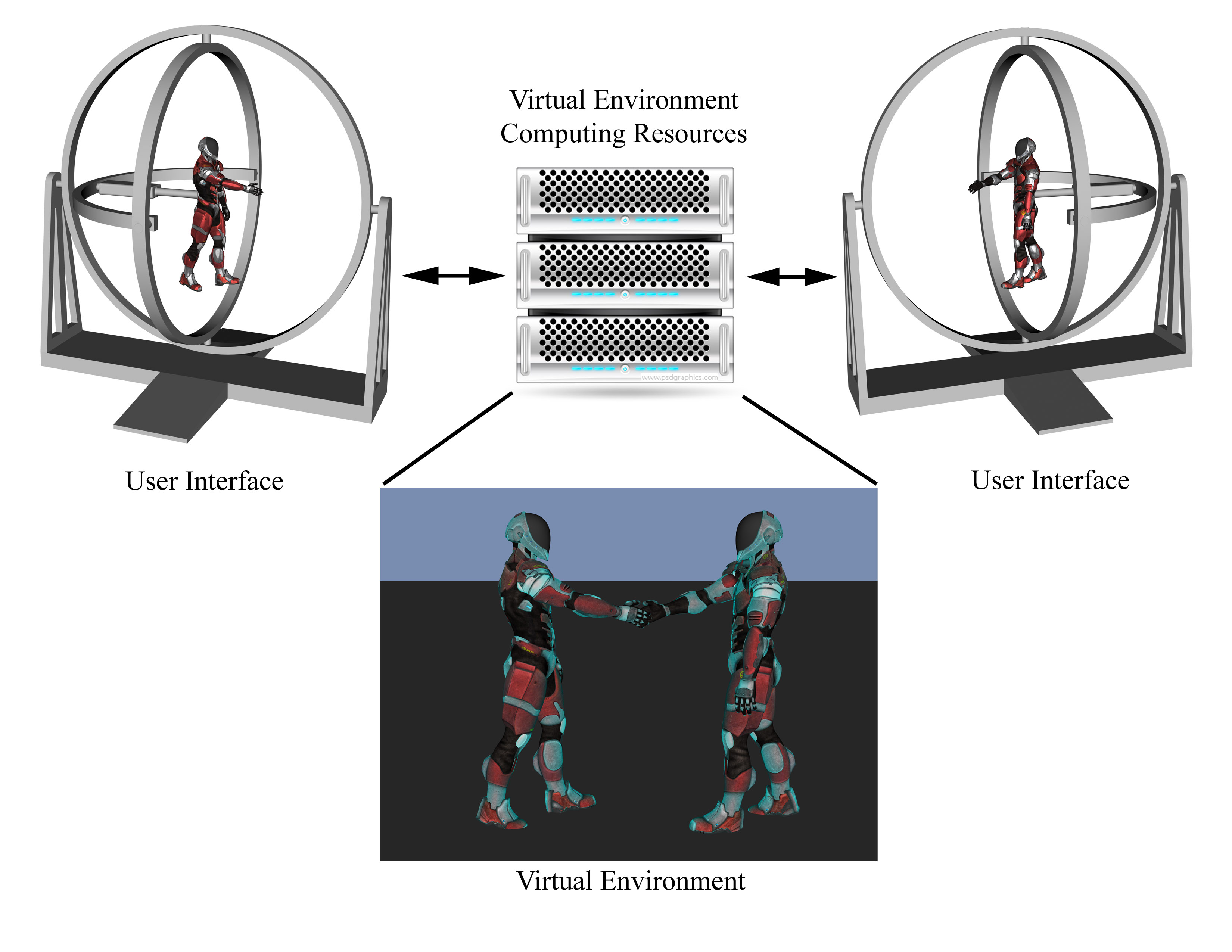
And Here’s What It Would Look Like…
But all of this cannot happen overnight, so the following figure shows a potential development progression. By starting simplistically with a single haptic degree of freedom (DOF), adding a gimbaled DOF next, and then simultaneously adding additional haptic and gimbal DOFs, each stage’s additional complexity in the exoskeleton, gimbal system, and virtual environment can be managed. Thereafter, two additional gimbal DOFs would be added along with several more haptic DOFs to achieve the final system.
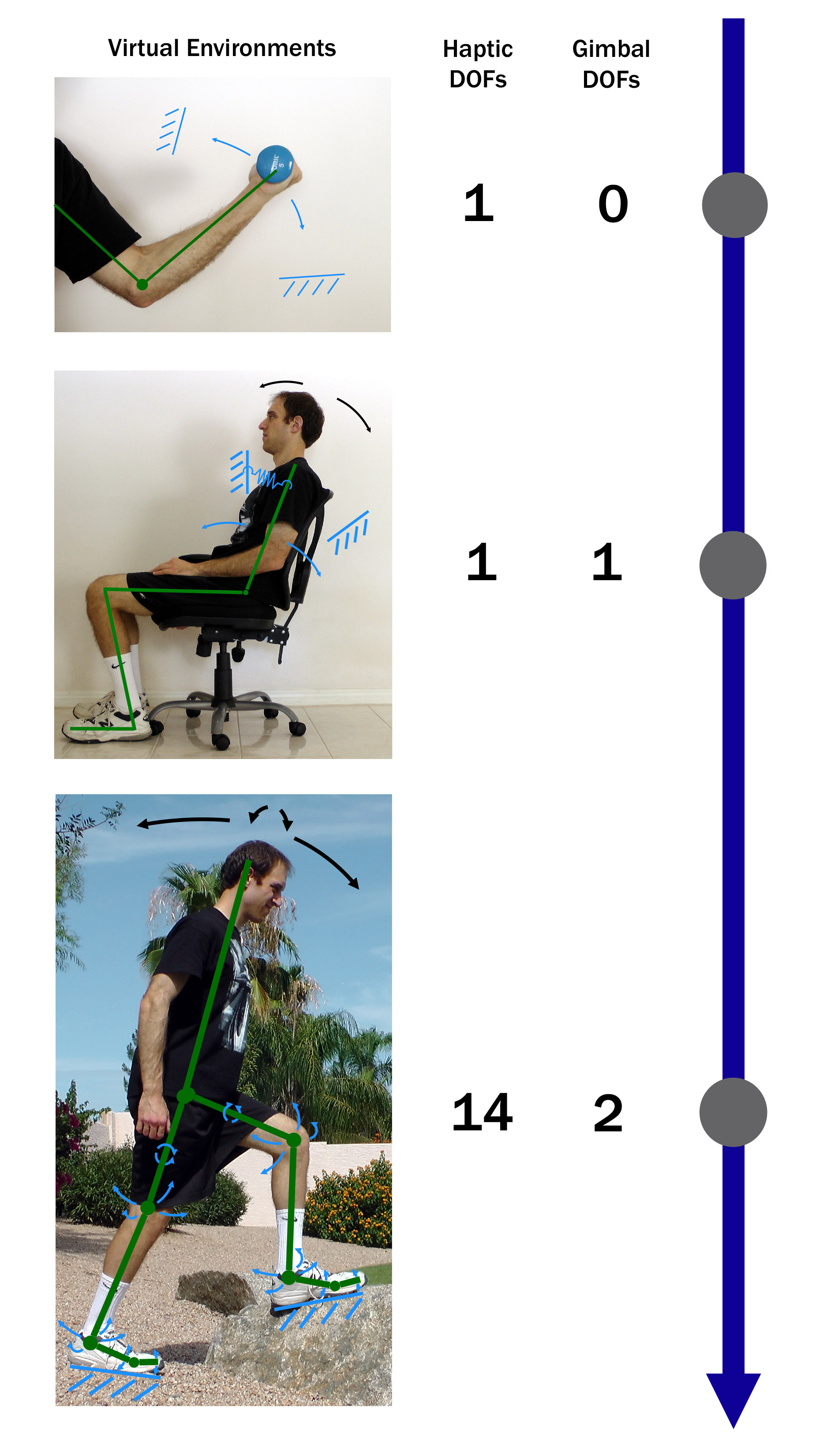
Green lines and dots correspond to the kinematic skeleton
Blue arrows indicate haptic DOFs, black arrows indicate gimbal DOFs
Additional blue markings indicate impedance or constraints imposed by the virtual environment
Single Degree-of-Freedom (DOF) Prototype
Now that we have an overall concept, we need to pick a starting point for developing the system. One of the key subsystems is the haptic exoskeleton, of which the most atomic part is a single joint actuator. Conveniently, the human elbow has only one DOF, so the perfect first prototype is a haptic exoskeleton for the elbow. Work progressed from this point as follows:
- Researched and prototyped actuation methods – selected DC electric
- CAD prototyping and Matlab calculations/simulations to find a near optimal arrangement of components needed to satisfy the velocity and torque requirements in a relatively compact form factor
- 3D printing of parts and assembly
- Electrical system component design, selection, and assembly
- Embedded control software design
- Initial Matlab graphical user interface (GUI) development
- Mechanical and electrical integration
- Revamped GUI based on QT for better real-time performance
- Embedded controller modifications and tuning
Here are the results…


Original MATLAB GUI

New QT GUI (Plot Page Shown Above)

Work is ongoing to improve the actuator and the controller. In particular, the controller is being optimized for two different scenarios: 1) fixed joint position with variable torque command and 2) constant torque command with variable joint position. Two rigs were constructed to test the scenarios. The video on the left shows the fixed joint position rig holding the actuator as the controller is commanded to apply sinusoidal torque commands with increasing frequency. The video on the right shows the driven joint position rig where a servo drives the joint position through a constant velocity full range sweep increasing in magnitude with each pair of passes as the controller is commanded to apply a zero torque command.
Unstable Controller: Gain and Phase Conditions Fail Testing

Stable Controller with Bandwidth >= 10Hz

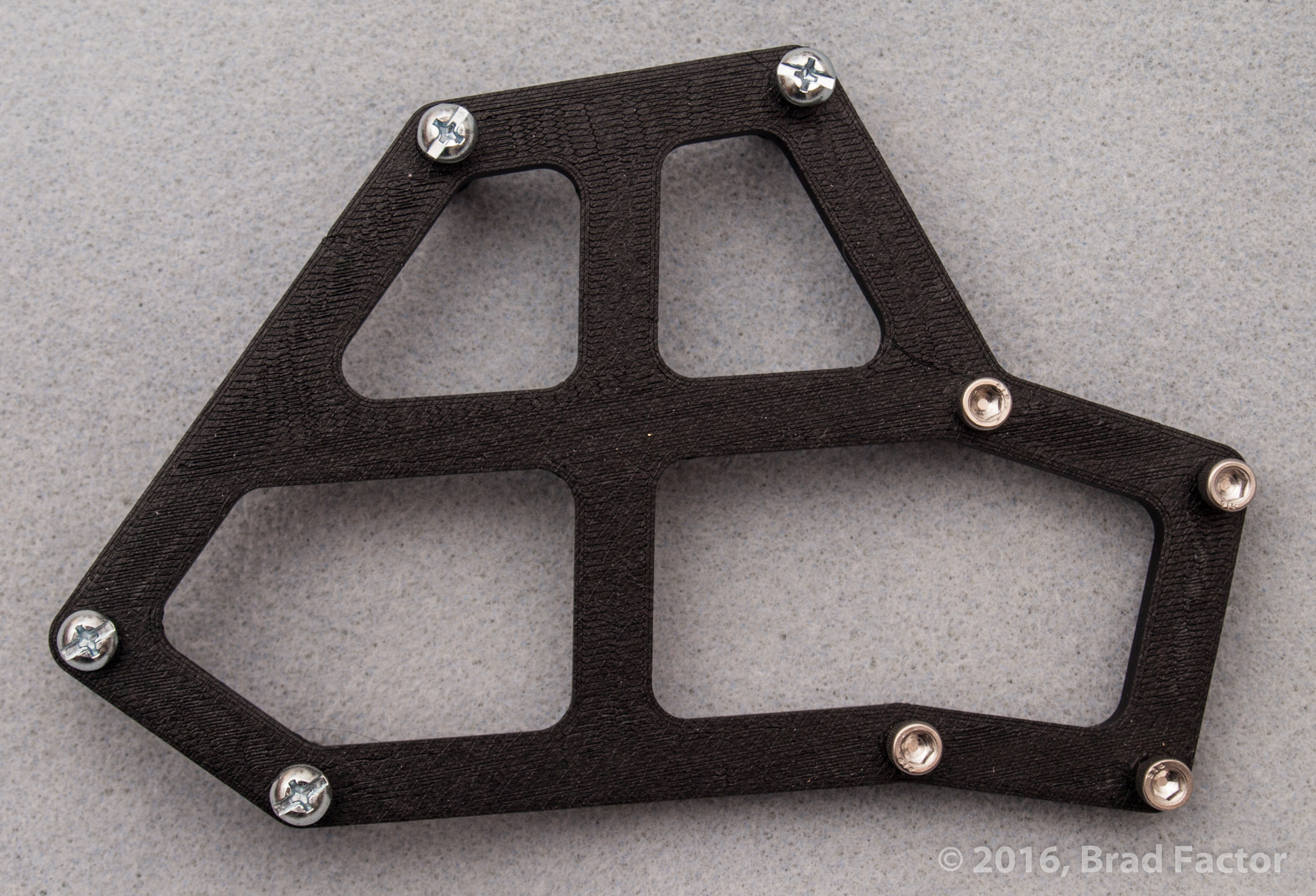
Mark II Single DOF Prototype
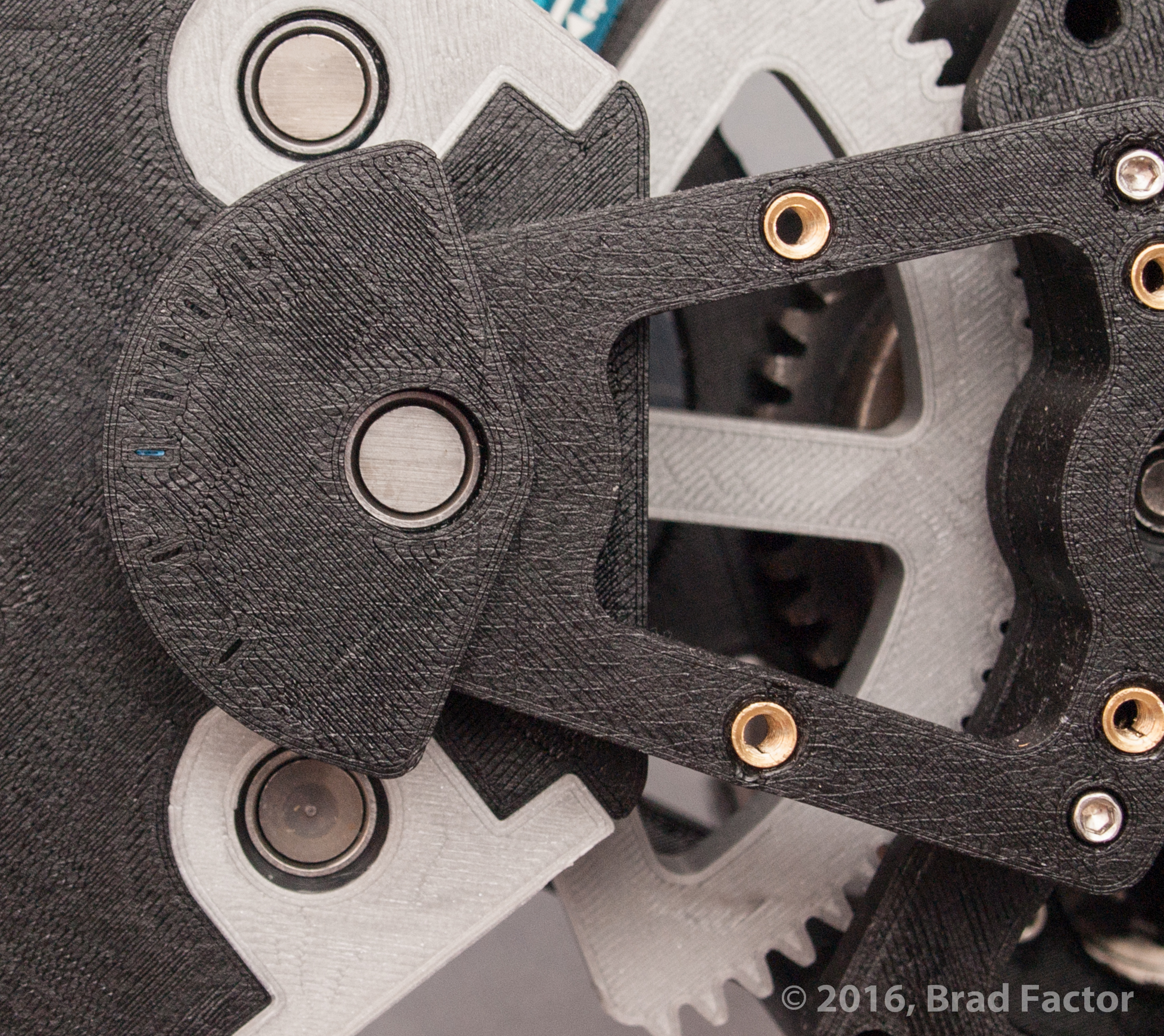
Incremental improvements were made to the original prototype, such as replacing the capstan drive with a more robust 3D printed gear drive, but eventually the number of desired modifications required a partial redesign and complete rebuild – enter the Mark II prototype.
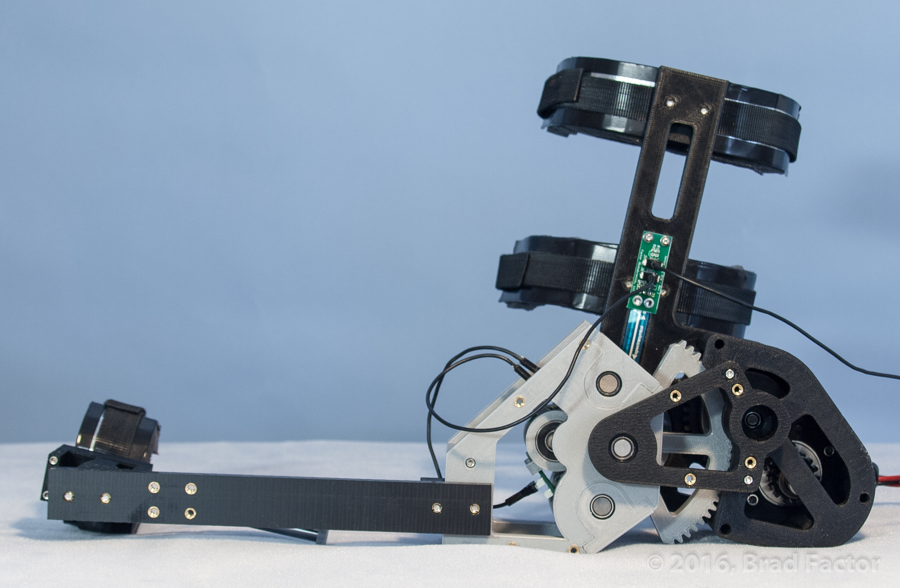
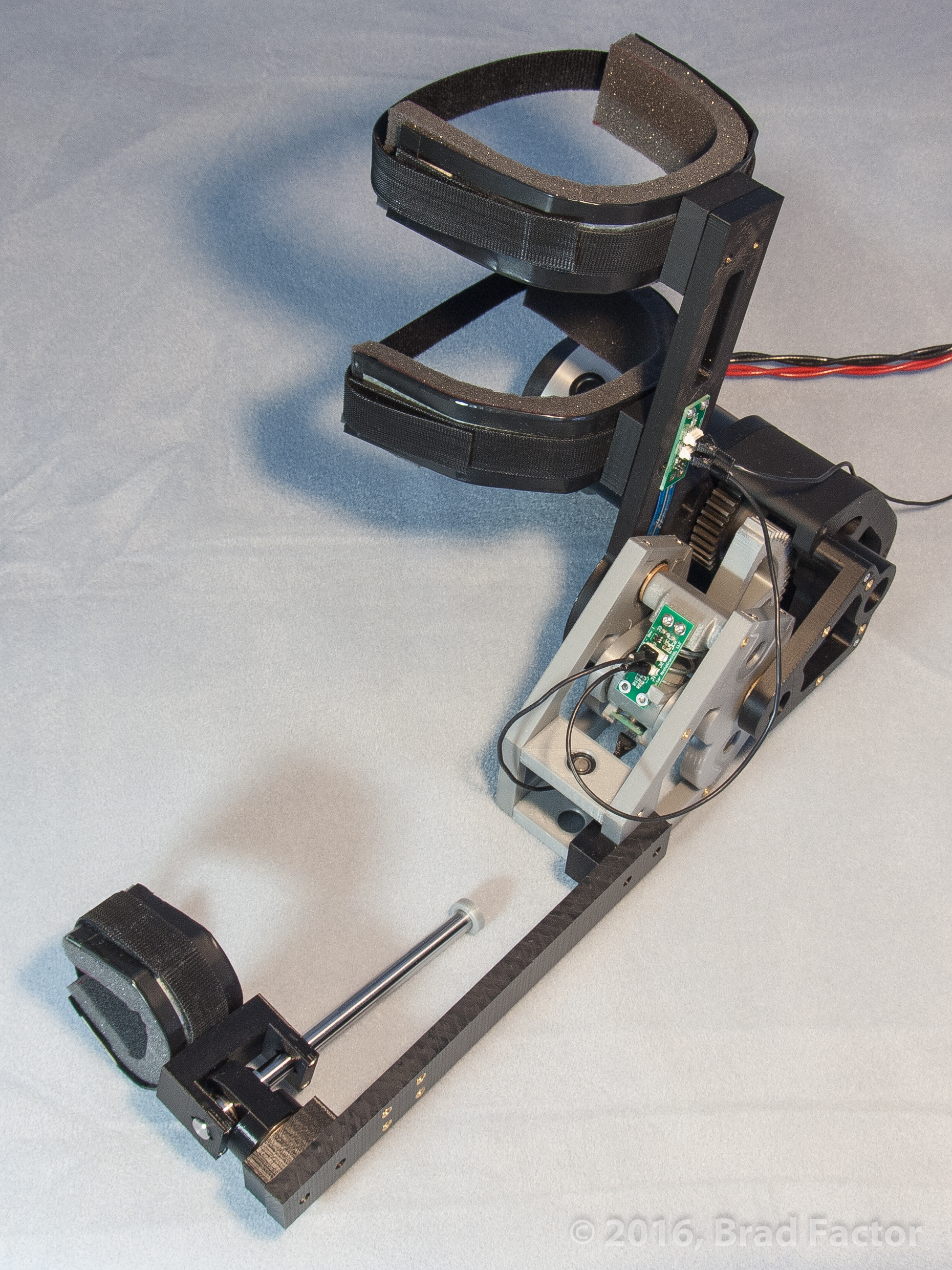
The major improvements are as follows:
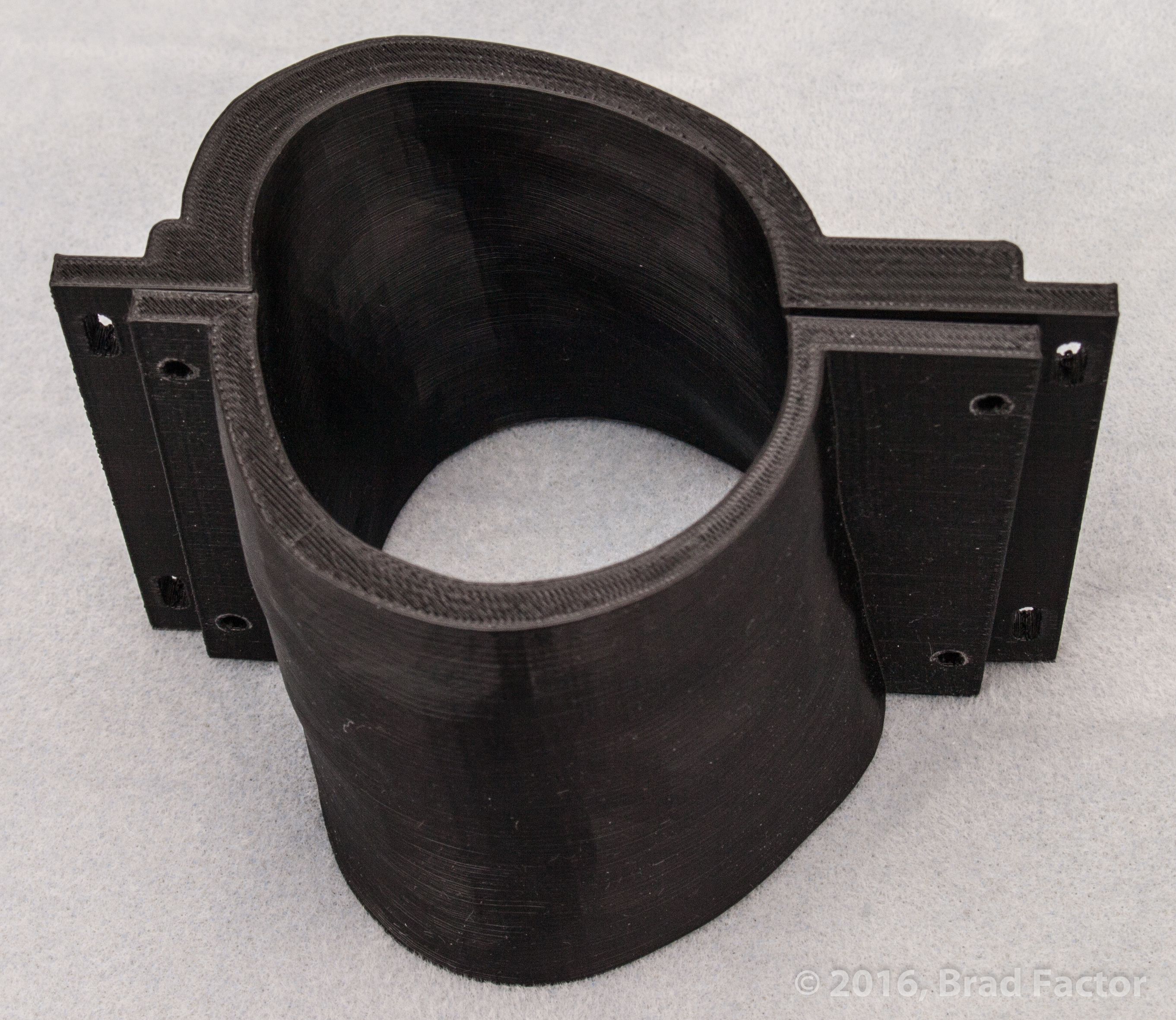
- Replacement of the COTS arm brace with integrated arm collars for greater design flexibility
- Addition of two passive degrees of freedom (one angular and one linear) at the lower arm to accommodate misalignment between the instantaneous center of rotation (ICR) of the human elbow and the exoskeleton elbow joint center of rotation
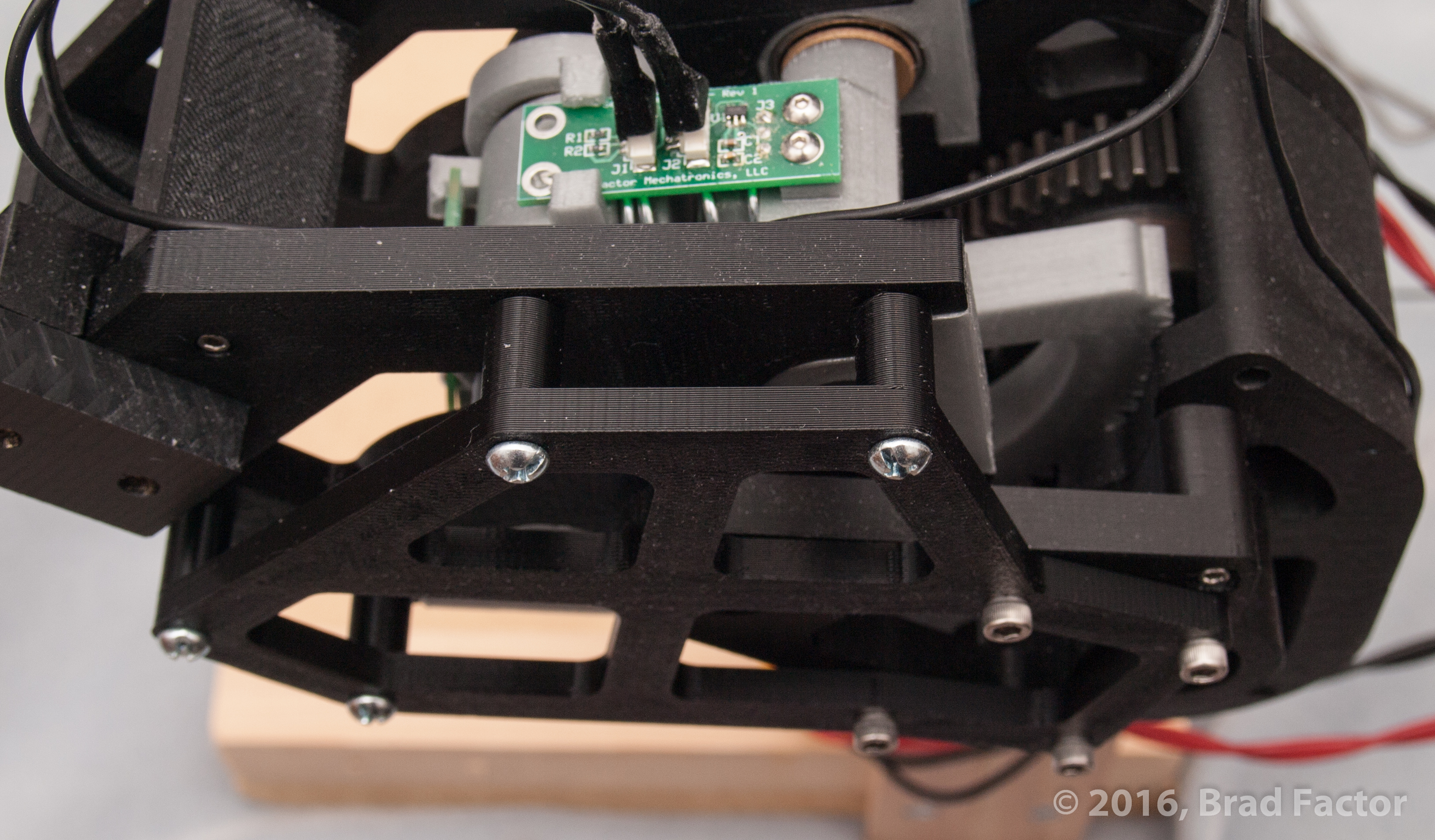
- Addition of an outer shaft bearing to symmetrically stabilize the actuator with an integrated safety cover around the gear drive
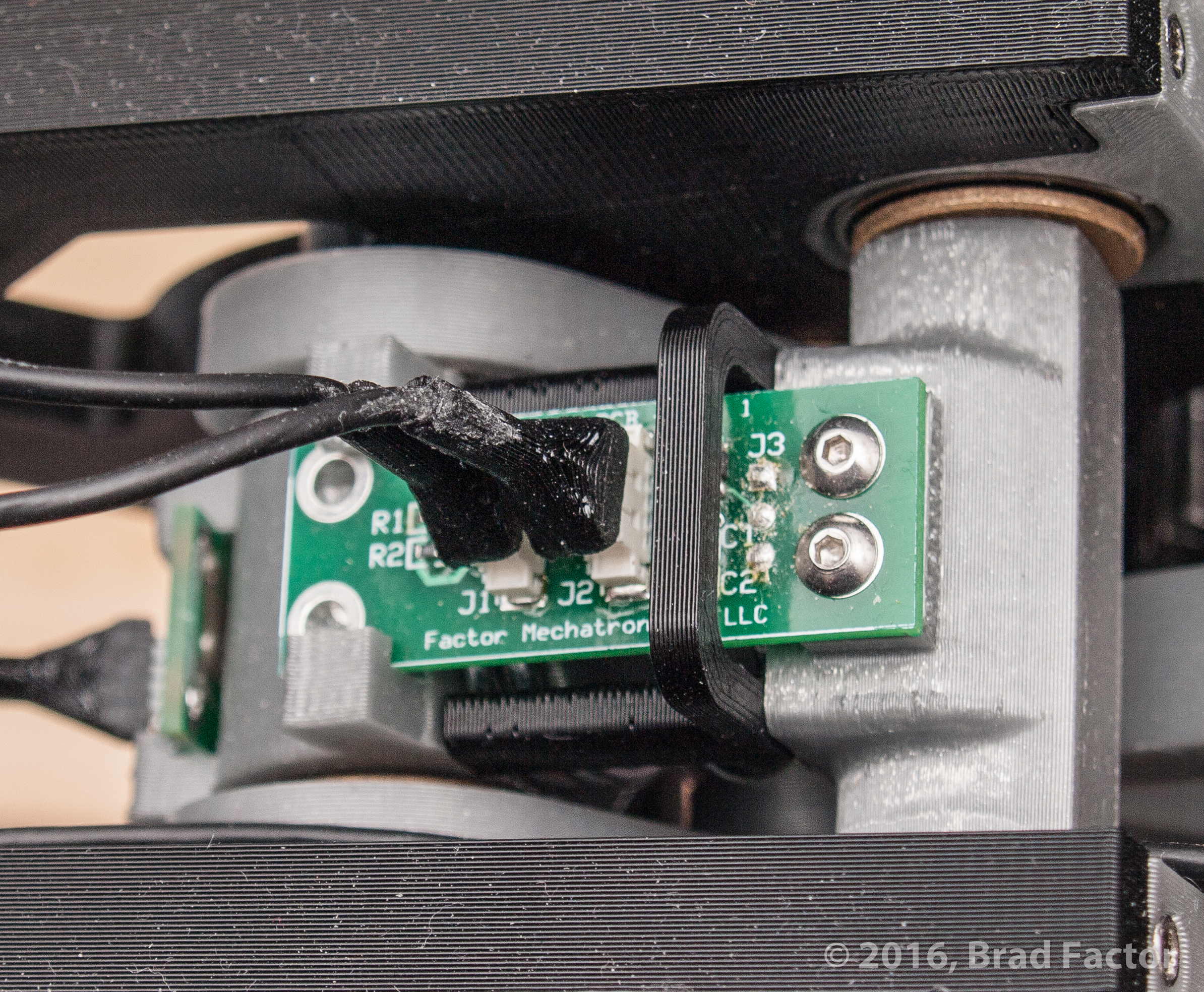
- Addition of integrated standoffs and guides for the linear ThinPot sensor ADC PCBs to ensure more reliable sensor performance
- Addition of strain relief hoods for cable connectors to prevent connector damage due to actuator motion
- Integration of the position tracking test rig by developing a removable servo and gear drive so that the actuator need not be removed from the exoskeleton for testing
- Integration of the torque tracking test rig by developing a removable hard stop brace so that the actuator need not be removed from the exoskeleton for testing
![]()
![]()
In addition to the physical rebuild, the microcontroller code was rebuilt from the ground up. After trying a solution based on FreeRTOS, a scheduled polling structure was finally established:
int main(void) {
    initialize();
    while(1) {
        if(newCycle_F == 1) startNewCycle();
        if(i2cCommComplete_F == 0) driveI2cCommunication();
        if(controllerComplete_F == 0) runController();
        if(cycleInProgress_F == 1) checkCycleCompletion();
        receiveSerialData();
    }
}
The startNewCycle() function checks for cycle overruns, clears flags, copies any serial messages to be transmitted from the Ping to Pong buffer, and loads the first byte to be transmitted if needed. Serial transmission is mainly handled by the USART TX Complete ISR to improve throughput. The driveI2cCommunication() function operates a state machine to request and read samples from each of the sensor ADCs. The bulk of the processing is performed by the runController() function, either directly or by calls to helper functions, which applies calibrations to sensor values, votes redundant sensors to a single value, processes received serial commands, handles requested calibration actions, and formats data for serial transmission; the runController() function will also include the actuator control law as well as state machines for test sequences. The checkCycleCompletion() function clears the cycleInProgress_F flag variable if all actions are complete for a given cycle. Lastly, the receiveSerialData() function parses incoming serial data and loads received commands into a circular buffer to be processed in the next cycle.
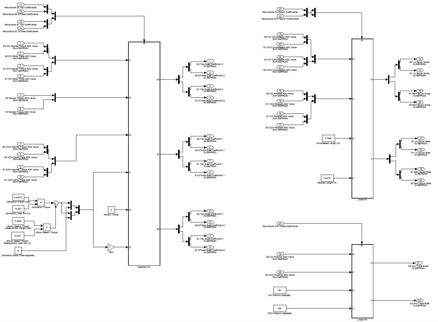
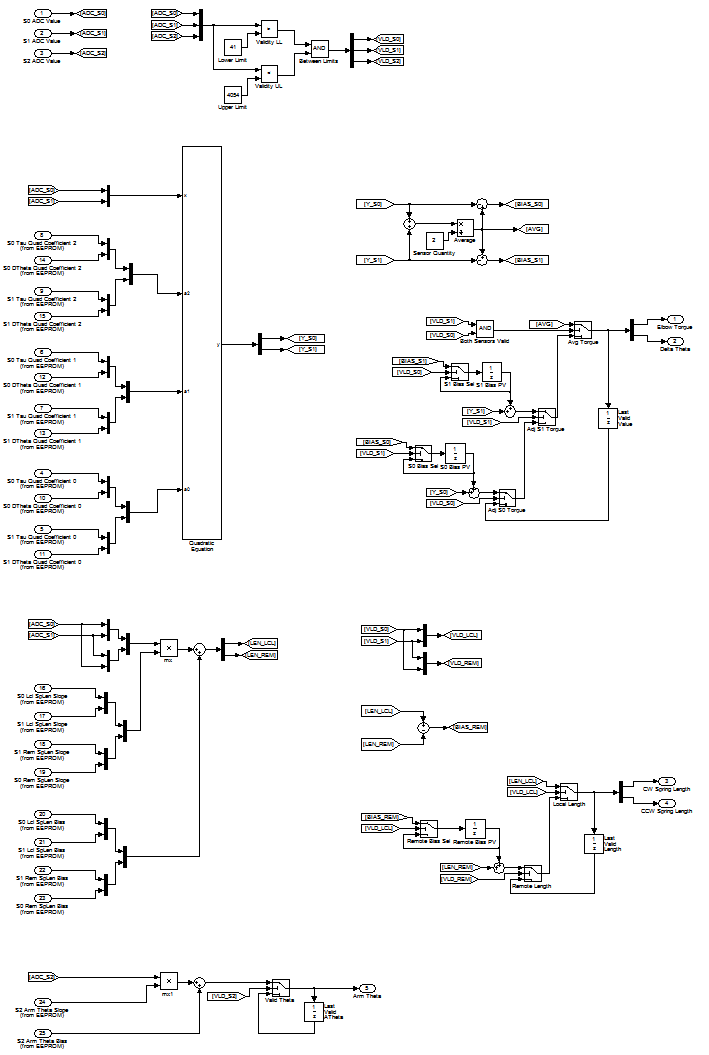
Prior to writing the code for sensor calibration and processing, the logic was modeled in Simulink:
To take advantage of the new features added to the microcontroller code, the QT GUI was also substantially redesigned:
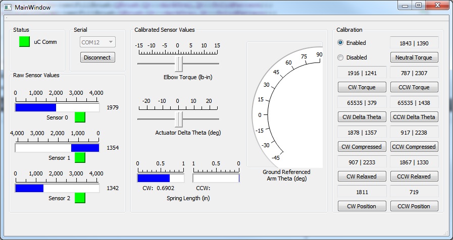
Raw sensor values are displayed in the leftmost pane, one for each linear ThinPot sensor and one for the rotary SoftPot sensor. The rightmost pane provides support for sensor calibration. The values displayed indicate the raw sensor values for the two spring length measuring linear ThinPots corresponding to each calibration scenario: torques applied to the actuator, offsets of the actuator from neutral, and spring lengths. The last two values are for calibration of the rotary SoftPot that provides joint angle. Calibration values are protected by an overall enable toggle and each value is updated by pressing the corresponding button. The center pane displays the resultant calibrated sensor values; some work remains, but significant progress has already been made.
3D Printing
3D printing technology is a fundamental part of my prototyping approach, first with Makerbot Replicator 2 printers at TechShop Chandler and later with a MakerGear M2 printer that I purchased.
Makerbot Replicator 2

MakerGear M2
As the printer would be inside a home environment with someone sensitive to airborne particles, I constructed an enclosure with a recirculating filter. After a little initial fiddling with the printer, it was time to make parts!


3D Scanning
Part of the challenge of human interface devices is the nature of the human body. From a mechanics standpoint, the best way to interface an exoskeleton with a person would be to bolt it directly to their skeleton, but nobody is going to sit still for that. Instead, one must develop a system that transfers feel and force in a way that is nearly transparent. Traditional interfaces consist of bent pieces of metal, padding, and velcro straps, as is the case with the COTS elbow brace that I am utilizing. However, I find that even short-term use can be uncomfortable as the brace does not adapt to the changing shape of my arm. In the process of designing a system that would adapt, I turned to 3D scanning to create a model of my own arm with which to design around. The 3D scanning technology that I am using is a Microsoft Kinect coupled with Skanect software. And don’t worry, that’s Adobe Premiere time dilation, not excessive caffeination.

User Comfort Experiments
As previously mentioned, user comfort is a difficult but critical problem in the success of exoskeleton design. To that end, several experiments have been attempted to determine the best physical interface between the human user and the exoskeleton.
The the experiment shown on the left is a two-part custom arm shell. This shell was developed from a model based on a 3D scan of my upper arm and 3D printed. The resulting shell was well-shaped to my arm in a relaxed posture, but noticeably uncomfortable in a flexed posture, due to the rigidity of the shell.
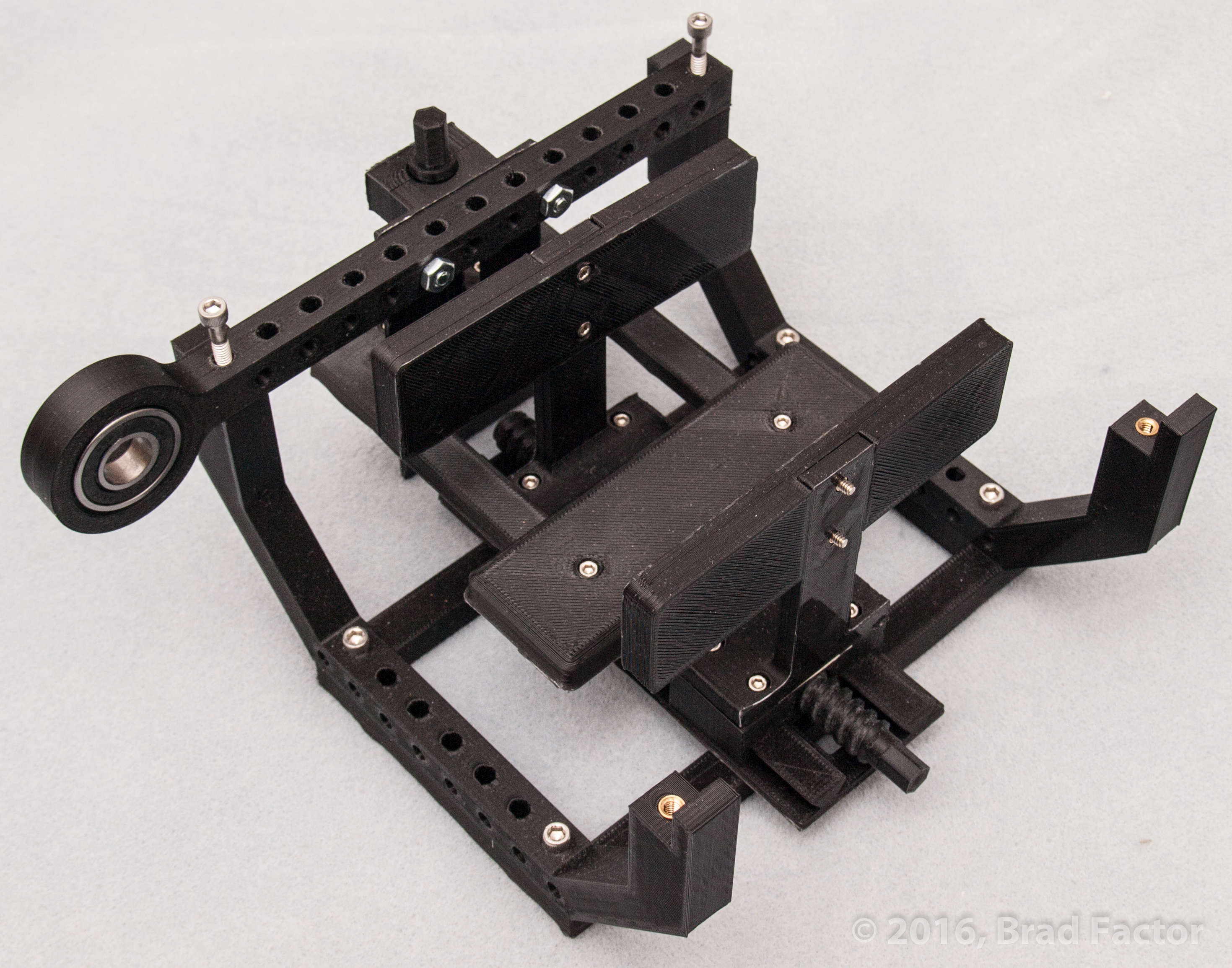
The next step was to determine if the arm could be comfortably constrained in certain planes while allowed to shift in others. The experiment in the center was designed to do just that by supporting the arm on the posterior face, and constraining it medially and laterally, while allowing for unconstrained motion on the anterior face. This was accomplished by designing and 3D printing an assembly of a framework, bracing structure, a symmetrical lead-screw moving carriages along a dovetail grooved rail, and an additional lead-screw and carriage. Although the rigidity of the structure was not quite sufficient, it did help to illustrate that while this adjustable arm clamp was more comfortable in some ways than the rigid arm clamp, it did not well-constrain the arm center line.
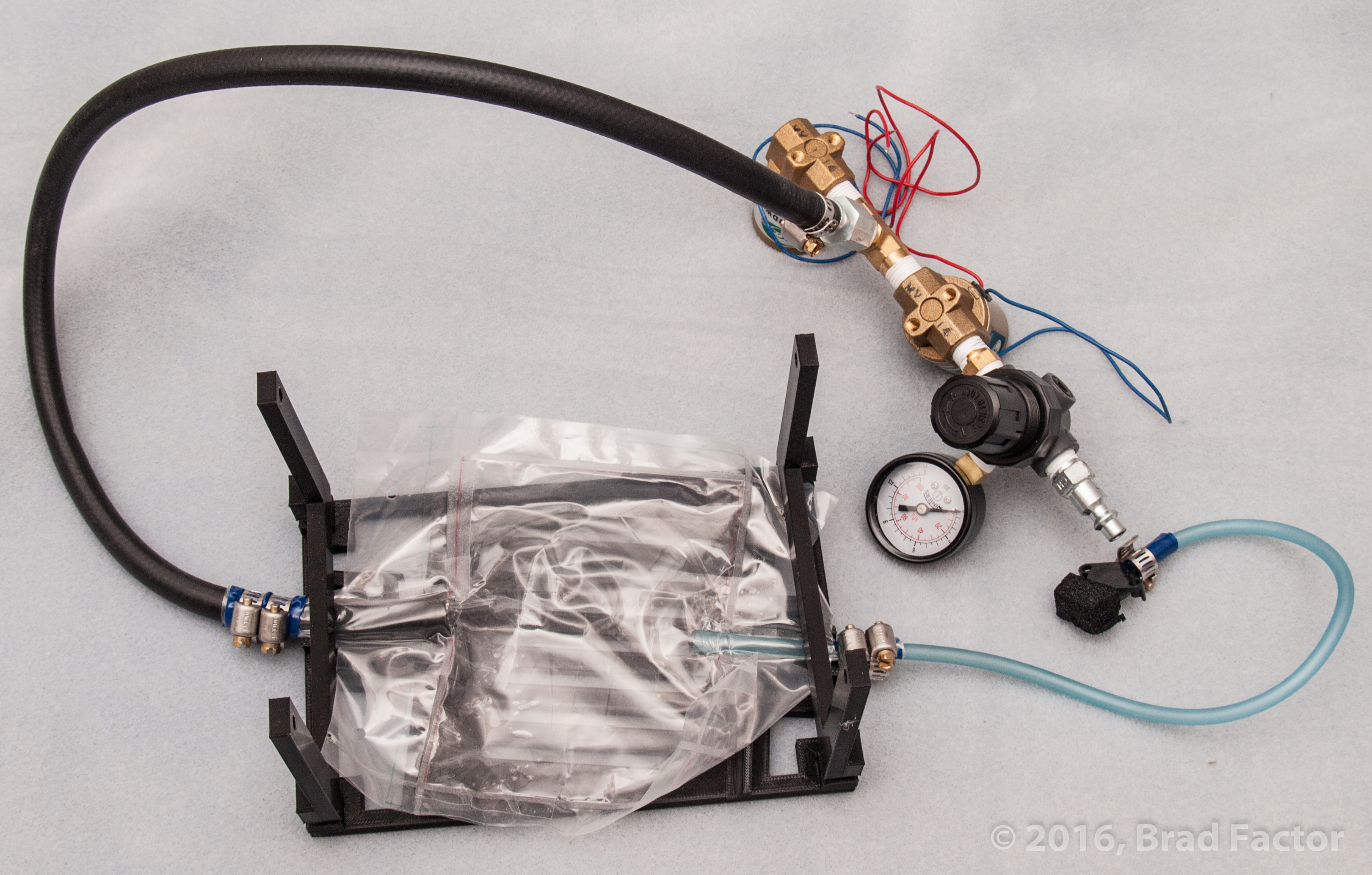
The last experiment so far, shown on the right, endeavored to roughly constrain the user’s skeleton to the exoskeleton center-line, while providing sufficient adaptability for comfort. A custom air bladder was designed and connected on one end, to an assembly of 2-way pneumatic solenoid valves and a regulator for controlling air into and out of the bladder, and on the other end, to an air pressure sensor. The bladder was mounted into a rigid structure with the concept that the user’s arm would be supported with a custom part on the posterior face while a control system adapted the inflation of the air bladder to maintain a desired pressure regardless of contraction or relaxation of the biceps and triceps. This way, a bias pressure could be applied to maintain the position of the user’s arm, and pressure could be increase commensurate with the joint torque command. There was a noticeable improvement in comfort, presumably due to reduced skin ischemia, and a future experiment is planned with a motor-driven force-sensing band in lieu of the pneumatic system for weight reduction and reduced response time. A video of one of the experimental sessions is also included below.